I’m not the first, only, or last person to say this – but one of the reasons I love home brewing is because it is a hobby that can satisfy so many different aspects of someone’s personality. The DIY opportunities within brewing has been an area that I really enjoy.

My most recent project has been to move to a counter flow chiller. The decision to go to this design actually took me a little while, as I debated and researched upgrading options. There is the multi-coil immersion chiller, coil-in-hose counter flow, and plate chillers. For me plate chillers were out because of my worries about being able to clean and sanitize completely. That was also my concern for coil-in-hose counter flow chillers. That lead me to looking at multi-coil immersion chillers and spending time perusing Jaded Brewing’s site. And low and behold, their Cyclone design. As luck would have it, there was also a comparison post on HomeBrewTalk using the Cyclone.
Now my interest was piqued. An easy to clean counter flow chiller? And I could copy the design and build on my own? Sold! So here we go into my build of a “Cyclone Clone.”
The parts list:
- 15′ of 1/2″ Type M copper pipe
- 15′ of 3/4″ Type M copper pipe
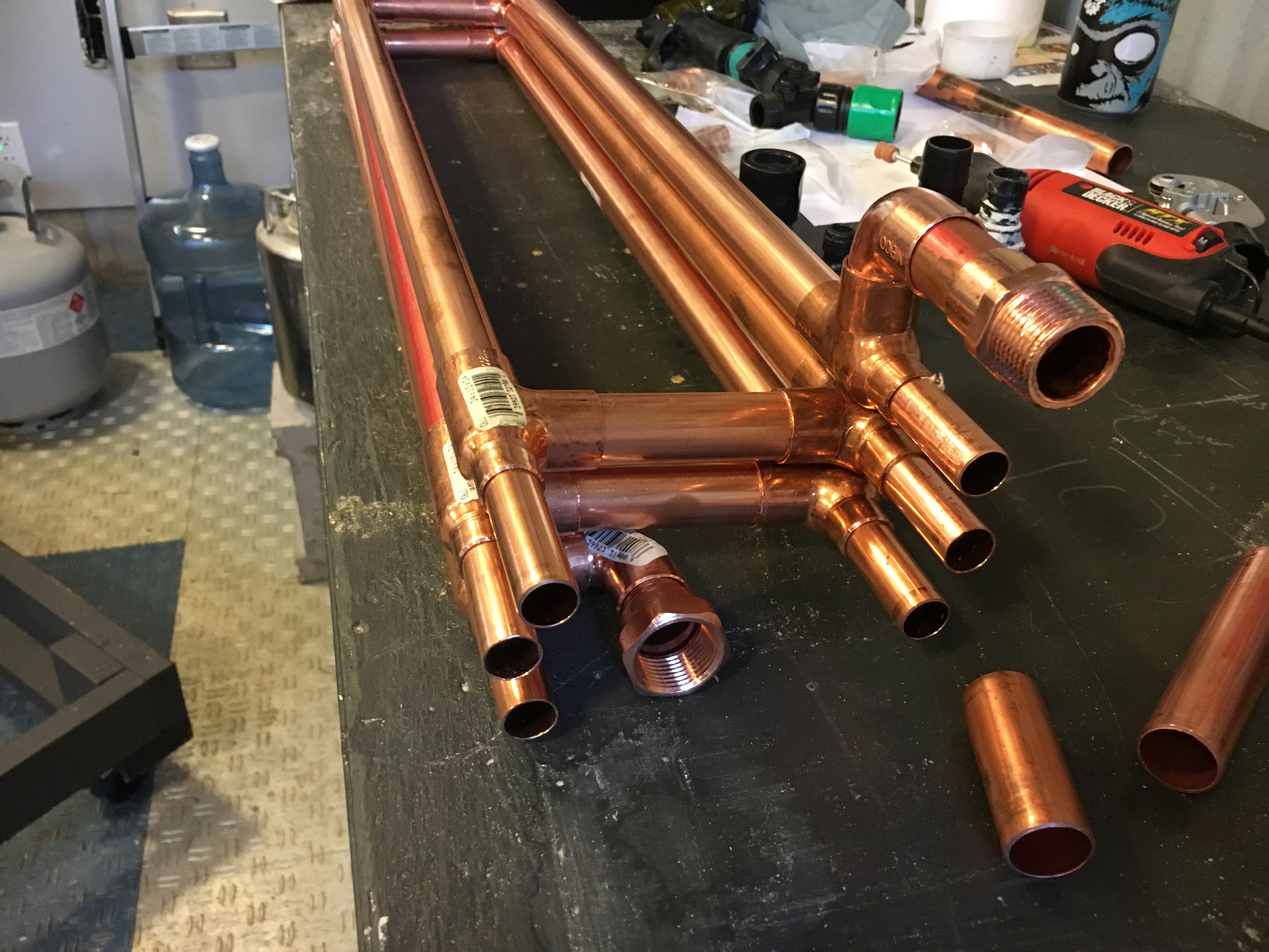
- 12 3/4×1/2×3/4 reducer tees
- 2 3/4″ elbows
- 2 1/2″ elbows
- 2 1/2″ male NPT connections
- 1 male and 1 female 3/4″ garden hose connections
- 1/2″ ID silicone tubing
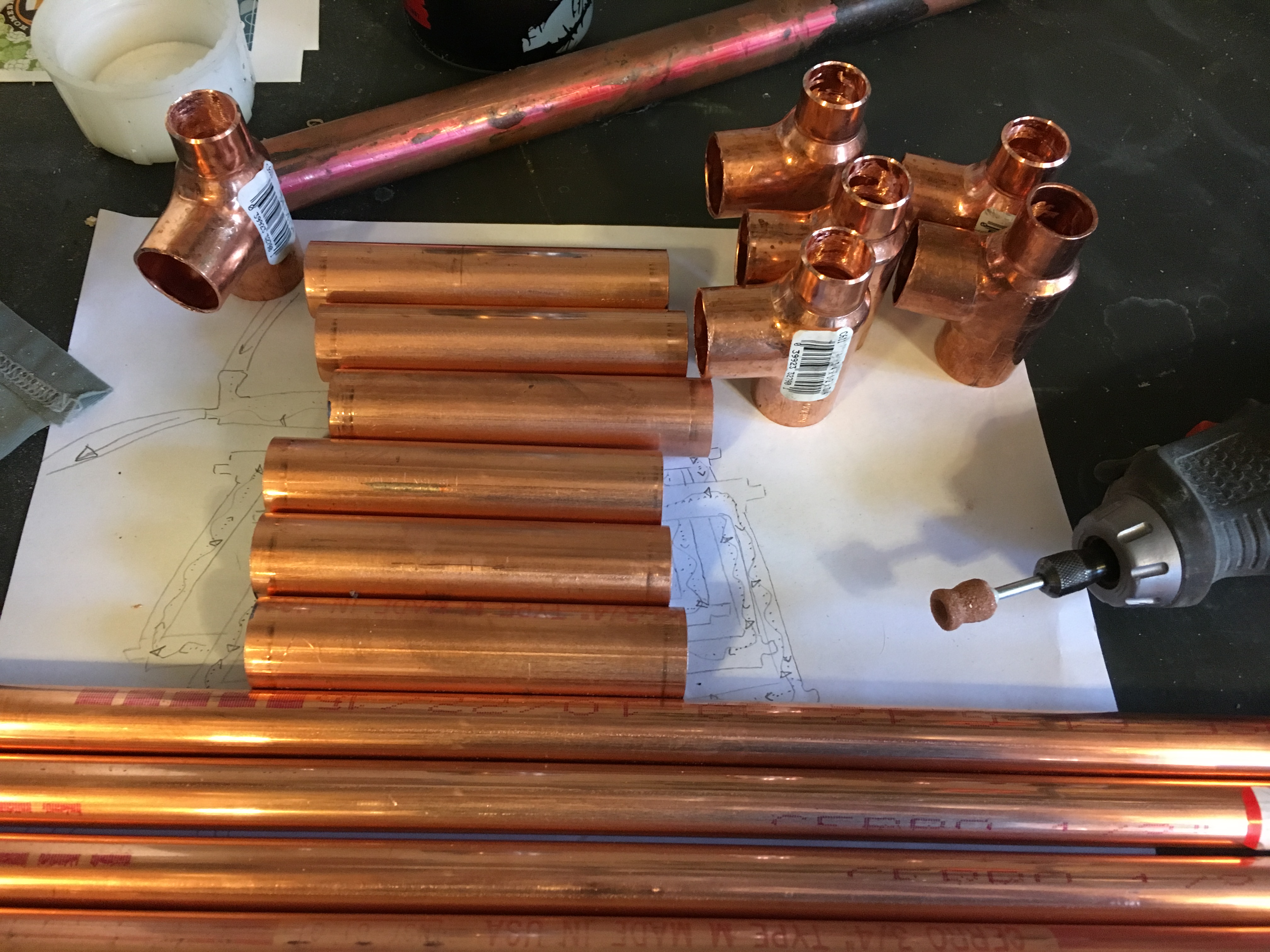
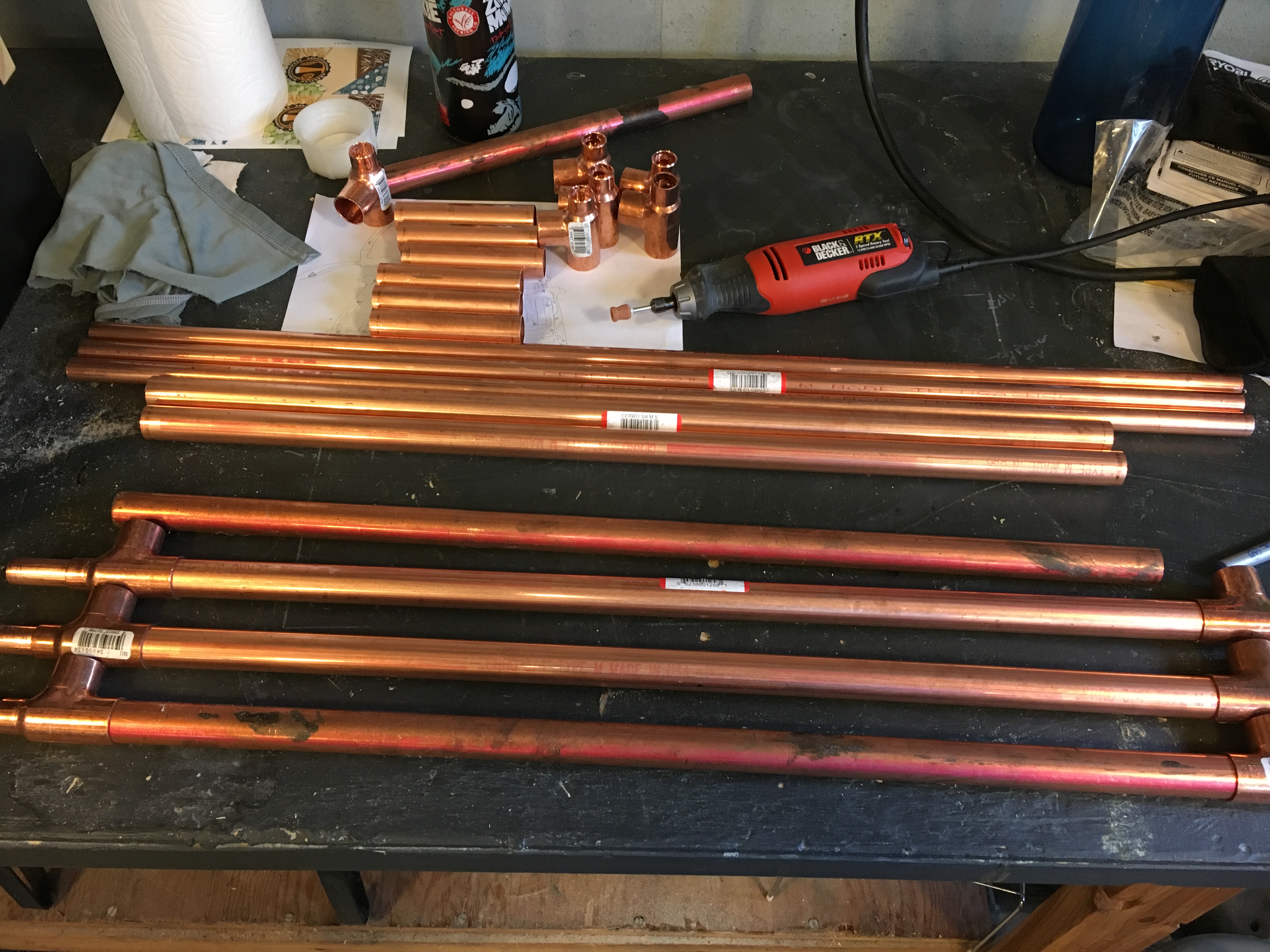
You also need a pipe cutter, silver solder, torch, and something to remove the lip in the tees. I used a rotary tool with a grinding stone.
The cuts:
The 1/2″ pipe is cut into six 30″ lengths. You can make these longer or shorter or add more layers to fit your brewery.
The 3/4″ pipe is cut to 24″ lengths, leaving 1 3/8″ roughly of 1/2″ pipe at each end to connect the silicone tubing.
The extra 3/4″ pipe is cut to five 4″ lengths to connect between the sections.
The tees:
On the 1/2″ side of the tees, you will need to grind down the lip on the inside that prevents the pipe from sliding through. I have read of people using files, drills, dremmels – I used the grinding stone on my rotary tool. It actually went pretty smoothly after the first one, but I would not want to do more than the 12 I did.
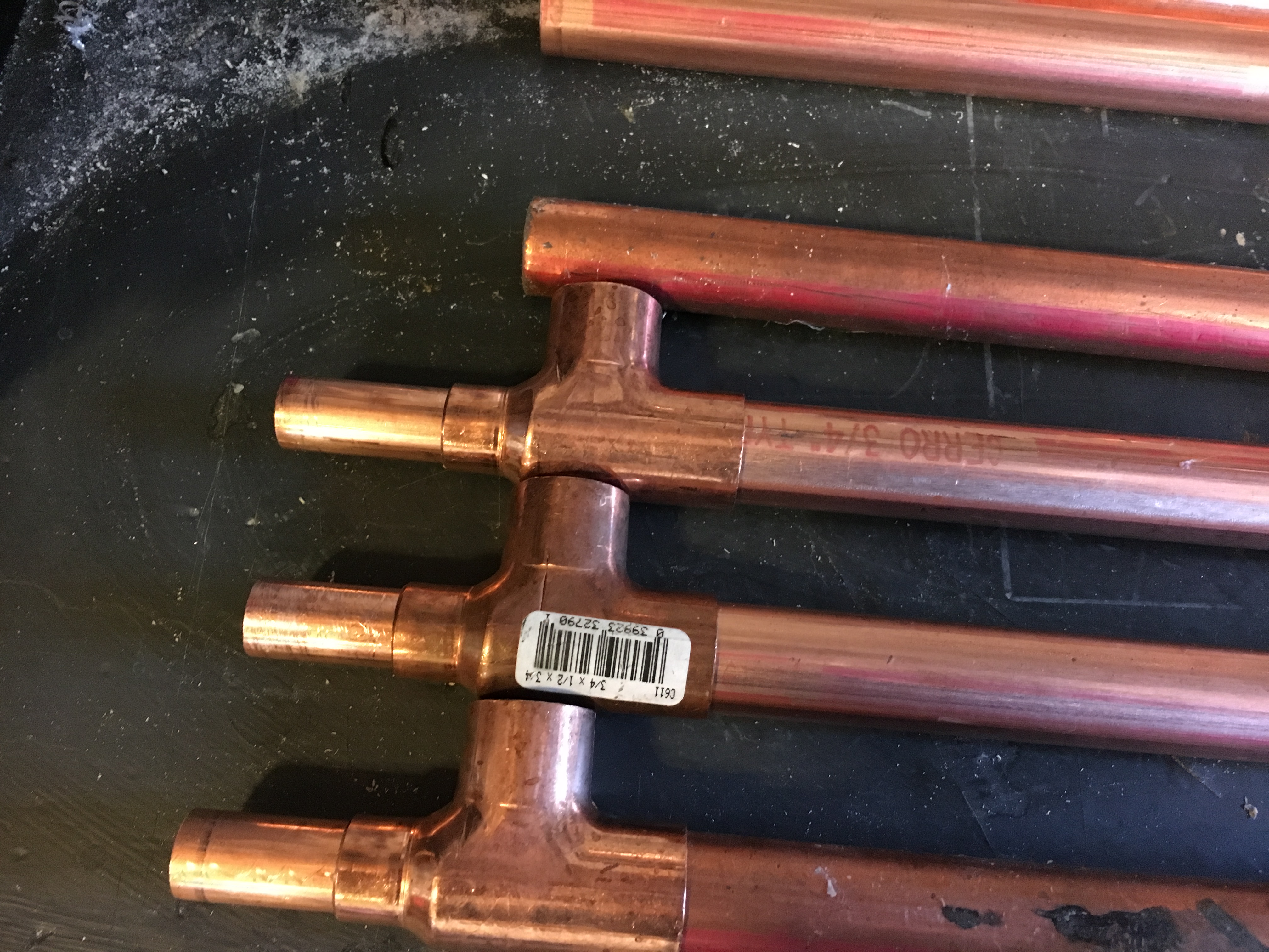
Once you have the tees modified, it’s time to dry fit. I highly recommend this step to make sure you have your connections figured out and that the water will flow in at the point the wort flows out, and that if you are mounting it fits as expected. I also used the step to make sure the angle and place meant of the elbows for the connections meet the plan.
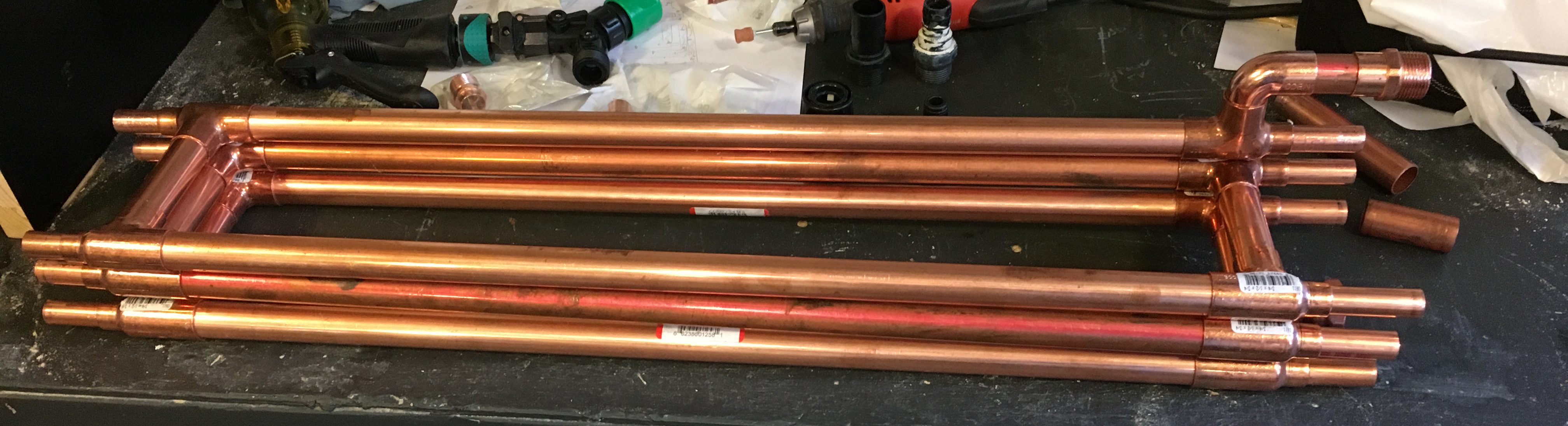
Assembly:
Now sand/clean the joints and apply flux. I found that 220 grit sandpaper and the air compressor made quick work of this step. I built it section by section, sanding, applying flux, and fitting.
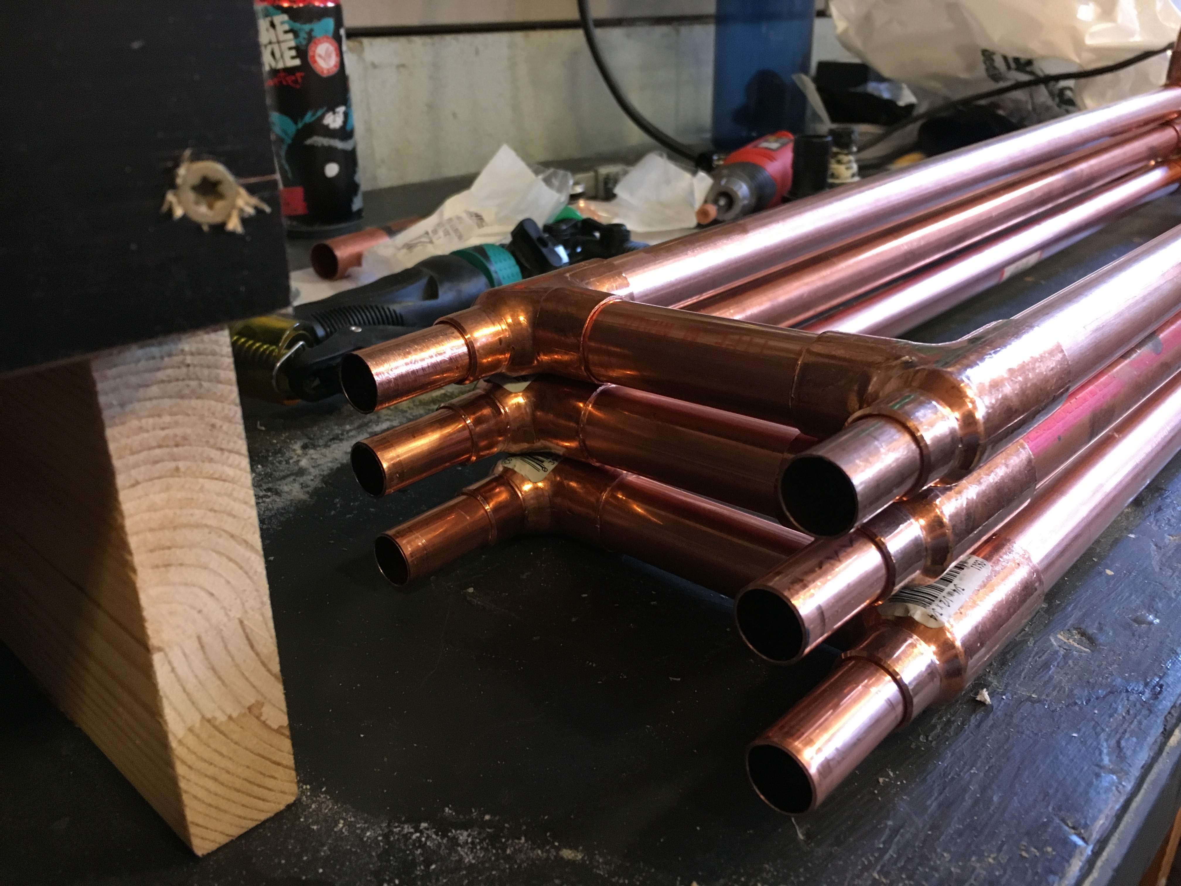
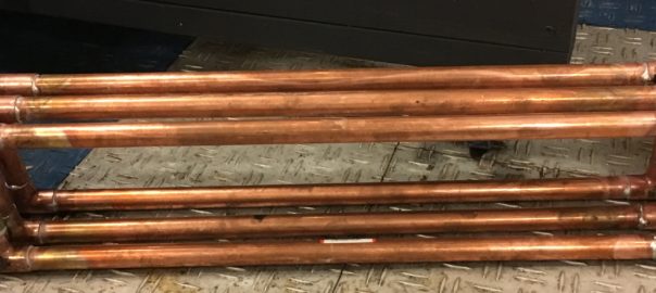
Then comes soldering. As you can see, my joints are not pretty. But I wanted the assurance of soldered joints vs compression fittings (plus the compression fittings are much more expensive and I’m “frugal”). I stared by heating the tees, then moving to the pipes. With a good amount of flux, the solder will flow around the joint pretty easily, but I still end up using way too much solder on each joint.
Then cut the silicon tubing to fit without kinking, mine were about 8” in length. The silicon will slide onto the ends and will stick to the coper holding it in place. The important point here, is to make sure you have the thick, 1/8” wall tubing.
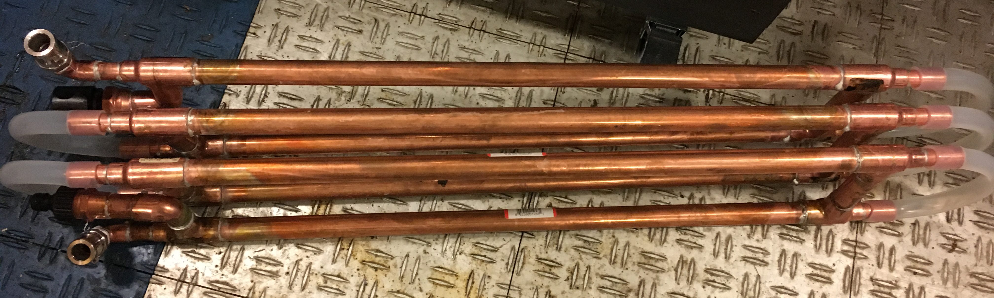
It’s a little hard to see in these photos, but I used quick disconnects for the garden hoses and cam-locks for the wort. This will be mounted on the back side of my brew stand. During the leak check, the garden hose fittings were what I had the most trouble with and had to crank them down hard into the copper connections. I will mount this on the back of my brewstand, which will be another post.